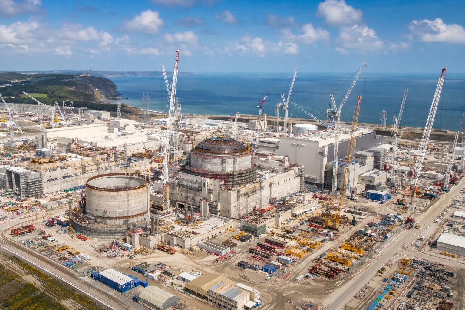
Helios-RH
Flight computers and sensor buses that keep working inside a reactor hall and beyond the Van Allen belts.
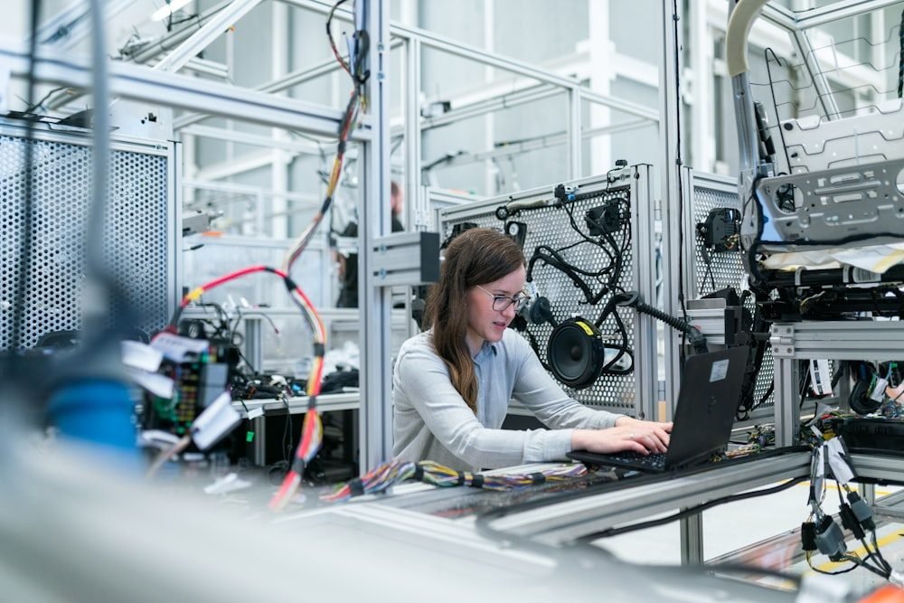
VGA-THM · Nuclear instrumentation
Measurement chains for places nobody is going to walk back into.
Thermion is our nuclear instrumentation line: in-core and ex-core neutron flux measurement, temperature and the safety logic that acts on them. It runs in research reactors and, increasingly, in advanced modular plant.
01 — Why it is built this way
Source range, intermediate range and power range on a single measurement chain using pulse counting, Campbelling and current mode with overlapping transitions. Operators see one continuous number instead of three instruments that disagree at the handover.
Response is established from detector geometry and a modelled flux profile, then confirmed by measurement. Chains recalibrated repeatedly against their own previous readings drift, and nobody notices for a decade.
Safety logic runs on separate hardware, separate power and separate cabling from the control and display path. There is no shared component whose failure takes both.
The people commissioning a 25-year installation are not the people who will maintain it in year eighteen. Documentation, labelling and diagnostics are written for them.
02 — Origin
Thermion started with a research reactor whose ex-core channel had been recalibrated so many times that nobody could reconstruct the original response curve. Each recalibration had been performed against the previous reading, and eleven years of small corrections had compounded.
The detector was fine. The drift was in a cable penetration whose insulation resistance fell with humidity, and in a preamplifier whose reference had aged exactly as its datasheet said it would.
We rebuilt the chain from the detector geometry outward and established the response from first principles. The full account is written up in our stories section — it remains the clearest example we have of why measurement is a system property.
03 — Architecture
From detector to plant. Note that the protection path and the control path separate immediately and never rejoin.
Callout 01
Rated to 550 °C with a known burn-up characteristic, so sensitivity loss over the fuel cycle is predicted and compensated rather than discovered during a surveillance test.
Callout 02
The part that most often causes drift and is most often blamed last. Insulation resistance is trended continuously, and a falling trend raises maintenance action before it reaches the measurement.
Callout 03
Mean-square voltage measurement bridges the gap between pulse counting and current mode, with deliberate overlap at both transitions so there is never a range where two methods disagree and neither is trusted.
Callout 04
IEC 61508 SIL 3, on separate hardware, power and cabling from the control path. Two-out-of-three voting on the trip demand, with a documented proof-test interval.
Callout 05
The final trip path is hardwired and de-energise-to-trip. No software sits between the trip decision and the breaker.
Callout 06
The control and indication path is fed from the same measurement but is electrically isolated and cannot influence the protection path in any failure mode.
04 — Detail
Detector physics is well understood. Nearly every real failure we have investigated was in the parts nobody photographs.
The failure modes that actually occur
Insulation resistance falls with humidity and thermal cycling. Trended continuously, because the trend is visible for years before the reading is.
A high-impedance charge signal is unforgiving of a marginal connection. Gold-plated, gas-tight, and inspected on a defined interval.
Voltage references age predictably. We budget for it in the calibration interval instead of finding it during a surveillance.
Commissioning and surveillance
Every calibration records both. A chain whose as-found is drifting is telling you something even when it is still in tolerance.
Interval derived from the SIL calculation, not from convention or from what the previous supplier happened to do.
Response confirmed against a modelled flux profile at commissioning, so there is a physics-based reference to return to.
| Detector type | Fission chamber, U-235 lined |
|---|---|
| Flux range | 10⁻¹ to 10¹⁰n/cm²·s |
| Measurement modes | Pulse, Campbell, current |
| Detector temperature rating | 550°C |
| Cable type | Mineral-insulated, Inconel sheath |
| Safety integrity level | 3IEC 61508 |
| Trip voting | 2-out-of-3 |
| Trip response time | < 120ms |
| Proof-test interval | 24months |
| Insulation monitoring | Continuous, trended |
| Installed life | 25years |
| Qualification | IEEE 323 / IEC 60780 |
Full interface control documents, environmental qualification reports and the traceability matrix are released under NDA. Ask for the document index rather than a brochure.
Request the document index05 — Qualification
Detector position and expected flux profile modelled before hardware selection, so sensitivity and range are chosen against physics rather than a catalogue.
Detector, cable, penetration and electronics designed as one measurement, because that is what it is.
Temperature, radiation and seismic qualification to IEEE 323 and IEC 60780, with the full test record supplied.
Full chain assembled and exercised across all three measurement modes including the transition regions.
Response confirmed against the modelled profile. As-found and as-left recorded from the first calibration onward.
Proof-test interval, trending regime and spares holding handed over as a maintainable programme, not a folder.

06 — Where it is built
Thermion electronics are designed and built in Chantilly. Type testing is done externally at accredited facilities — seismic and environmental qualification needs equipment we have no business owning.
Commissioning happens on the customer's site, and it is where the programme is actually won or lost. A chain that reads correctly on a factory bench and cannot be verified in its installed geometry has not been commissioned.
European installations are supported from Farnborough, which keeps our commissioning engineers within a day of most of the reactors they look after.
07 — Who uses it
Two university reactors and one national laboratory run full Thermion chains.
Instrumentation packages for two modular reactor developers, currently in the licensing phase.
Measurement support on three legacy sites where the original instrumentation records were incomplete.
Related
Flight computers and sensor buses that keep working inside a reactor hall and beyond the Van Allen belts.

A triplex flight control and display suite certified to DO-178C Design Assurance Level A.
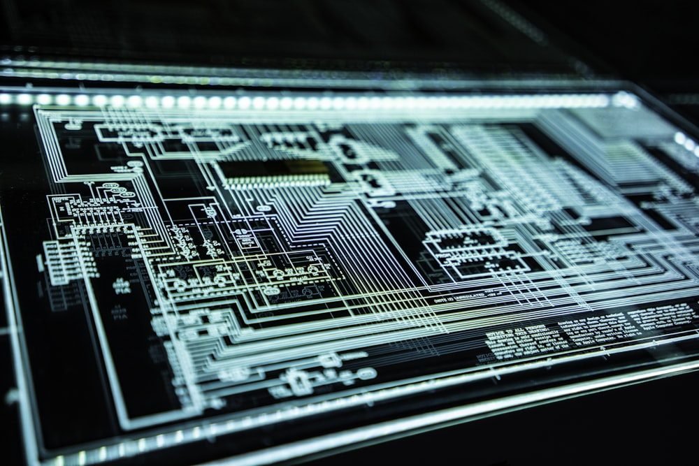
Command, telemetry and attitude electronics for small satellite platforms in low and medium Earth orbit.
Next step
Tell us what it has to survive and how long it has to keep working. We will tell you whether Thermion is the right answer — including when it is not.
Talk to an engineer